Building a PC isn’t easy for everyone, but if you’re someone who’s planning on doing it soon or just a PC enthusiast who’s passionate about PCMR, then this is the perfect blog for you. In this column, we will be discussing the nervous system of any computer, the motherboard, because the motherboard is the most important component of any computer, as everything from the CPU to the GPU is connected to it.

But the motherboard is a very large component to understand. So, let’s start by understanding all the motherboard connectors, from the main 24-pin and EPS connectors to the different types of RGB connectors.
To understand all the motherboard connectors, we’ll start with the most important connectors on your motherboard and then move on to the basic connectors. If you’re curious about how all the connectors on your PC’s motherboard work, this is the perfect protocol to find out.
Table of Contents
ATX 24-pin Power Connector
The 24-pin ATX Power connector is probably one of the most important connectors on the motherboard. To understand the 24-pin power connector, you need to know how all the components of your computer are powered. The simple and short answer is that the power is delivered through your power supply at 12 volts, which is then converted for the individual components such as SSDs, hard drives, and RAM.
The 24-pin ATX power connector comes directly from your power supply and is connected to your motherboard in a specific way, as it is split into two lines with 12 pins each, with every single pin used for power and some for ground (8 to be exact).
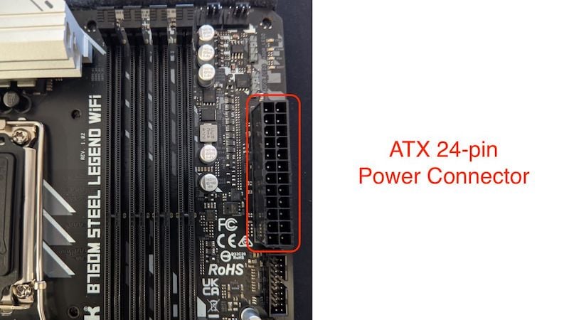
The ATX 24-pin power connector is used to divide the power between the different components of your motherboard. If you are not using a modern PC but one from the 90s to early 2000s, then these PCs have a 20-pin power connector instead of a 24-pin power connector. This may sound absurd now that all motherboards now come with 24-pin connectors, and all power supplies come with 24-pin motherboard connectors. But the more important question is why they had to change from 20-pin power connectors to 24-pin power connectors.
The answer is quite simple: the components in your PC are becoming more and more power-hungry and, therefore, need to be supplied with more and more voltage. Otherwise, there will be bottlenecks in your PC, and some components will even stop working. That’s all you need to know about the 24-pin ATX power connection. Now, let’s move on to the next 8-pin EPS motherboard connectors or connectors.
8-pin EPS Connector
The 8-pin EPS connector stands for (Entry Level Power Supply) and is an important connector for your CPU in all motherboard connectors. It is located on the top left of all motherboards if we look at it with the layman’s eye. We will understand that it looks very similar to the PCIe connector, but both are the same counterpart to each other. If it is an 8-pin EPS connector, it supplies power to the CPU, but doesn’t the 24-pin power connector supply power to all components?
The 8-pin EPS power connector is specifically designed to power the CPU, as modern CPUs require a lot of power. Although the 20-pin power connector is only designed for 12 volts, the power requirements of current processors exceed what the 24-pin connector can supply. In the past, CPUs only worked with 4-pin EPS connectors, but modern CPUs can require up to (4+4)pin x2 to deliver the appropriate amount of power.

SATA Connectors
SATA connectors or SATA ports look like L-shaped connectors on the plug and are usually located on the right side below the 24-pin power connector (usually). It’s used to connect HDDs and SATA SSDs to your PC, but it’s not the fastest port when it comes to speed, so its popularity is waning because most people are switching to NVME-based SSDs for better data transfer rates. If you want to check the speed of your storage device, check out our article on the best disk speed test apps.
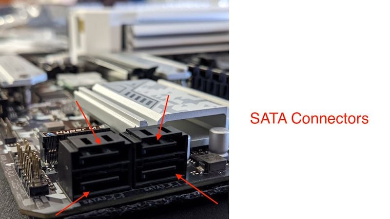
Modern motherboards can usually connect up to 4 SATA devices, and all SATA motherboard connectors are labeled as SATA1, SATA2, SATA3, and SATA4. To connect an HDD or SSD to a SATA port, you will need a SATA data cable that connects to your storage device on one end and to the motherboard on the other.
It is important to note that the SATA ports on your motherboard are only used for data transfer, while your power supply must power the SSD or HDD you use with these ports. Only then can you use your storage devices. Now that you know about SSDs, let’s discuss how to connect USB to our motherboard.
USB Connectors
USB ports on the motherboard and USB ports on the motherboard may sound the same and offer the same functionality in some ways, but both look different and can even be used differently. Let’s explain what the difference between them is. While the USB ports on the back of your motherboard can be used directly to plug and play, there are two other different types of USB connectors on your motherboard, namely USB 2.0 connectors and USB 3.0 connectors.
-
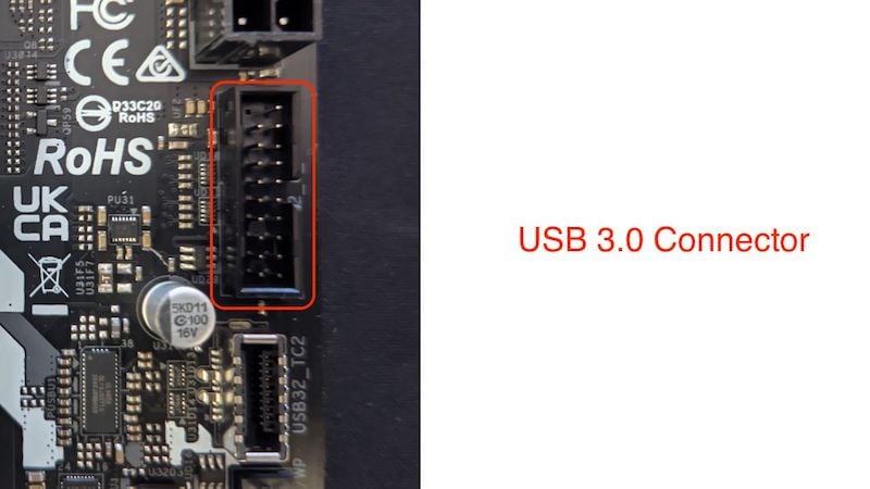
USB 3.0 Connector
The USB 3.0 connector is used to connect the USB ports on the front of your PC case. It offers speeds of up to 5 GB/s and, in most cases, is located near the bottom right of your motherboard, directly above the SATA connectors. The connector has a total of 19 pins, 10 up and 9 down, and can be connected in a single way.
-
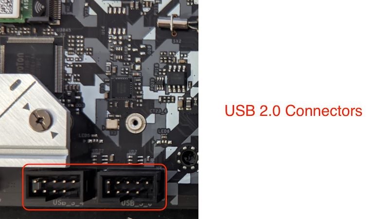
USB 2.0 Connectors
There may be multiple USB 2.0 connectors on your motherboard, unlike USB 3.0, which has only a single connector but can power multiple USB 3.0 ports. USB 2.0 connectors consist of a total of 9 pins and are located on the bottom half of the motherboard. Although both USB 2.0 and USB 3 motherboard connectors are used to output USB devices, the two are not compatible with each other and cannot be connected as they both use different cables.
Fan Connectors / Fan Headers
Every motherboard has 3 or at least 2 types of motherboard connectors/headers that control your PC’s fans. Everyone should have fans in their PC case because they are important for airflow and maintaining system temperature. There are usually 3 types of system fan headers, all of which we will cover:
-
CPU Fan Connector
The CPU fan header is used directly to connect the CPU fan to the motherboard and even control its speed. It is usually located on the top of the CPU socket. It is the second most important motherboard connector for your CPU. It controls and regulates the speed of the CPU fan depending on the CPU temperature to ensure optimal performance of your CPU. It is usually a 4-pin CPU connector, as a 3-pin connector does not help regulate the fan speed and operates at a fixed fan speed of 12 volts.

-
System Fan Connector
Among all motherboard connectors, the system fan headers are the most underrated connectors. While most budget motherboards are equipped with 1 or 2 system fan headers, most mid-range and flagship motherboards can be equipped with up to 4 system fan headers. The system fan header usually has 4 pins instead of 3 so that the motherboard can easily control the system fans and does not run at full speed all the time. They are usually located near the front panel connectors on the bottom of the board and can sometimes be present near the CPU fan connector.
-
Water Pump Connector
There is not much difference between a system fan connector and a water pump connector. In most cases, the only difference is the amperage, as a CPU pump requires much more power than a normal system fan to function properly, while different motherboard connectors cannot be used and connected together. The water pump connector can also be used as the system fan connector. The Water Pump connector is usually located right next to the CPU fan connector.

It is also a 4-pin connector, but when we use an AIO cooler for the CPU, the water pump connector is usually only connected to 3 pins because the AIO pump needs to run at full speed all the time.
RGB/ARGB Connectors
The RGB/ARGB connector offers no performance or functional advantages, and on most inexpensive motherboards, it is not necessary for them to be present. These motherboard connectors are usually located near the Front Panel Connectors on the bottom of the motherboard. It can be a 3-pin header or a 4-pin connector. Let’s take a look at how they differ.
-
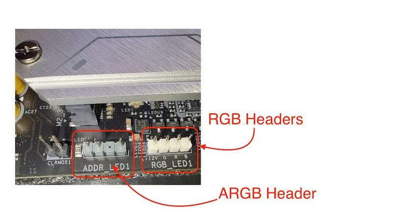
RGB Connectors
RGB stands for Red, Green, and Blue. RGB connectors are 4-pin connectors that power all RGB peripherals in your system; these motherboard connectors work on a manual basis, and all devices connected via these connectors can be controlled via an external hub or an RGB controller on your PC case.
All RGB devices operate via analog signals and cannot be controlled via the motherboard utility.
-
ARGB Connectors
ARGB stands for Addressable RGB. These motherboard connectors can be easily distinguished by the fact that RGB connectors use a 4-pin connector, and ARGB connectors on your motherboard use a 3-pin connector. These motherboard connectors are called ARGB connectors because they are addressable and can supply power to individual lighting components so that they can be easily connected and controlled with your specific motherboard utility software.
While most inexpensive motherboards today only come with one ARGB header and multiple RGB headers, it’s important to note that earlier motherboards did not ship with these motherboard connectors, as RGB did not exist in the early 2000s.
It is also important to know that both RGB and ARGB connectors require a different voltage: The RGB connector operates on 12 volts, and the ARGB connector operates on 5 volts.
Front Panel Connectors
These motherboard connectors are probably the most complicated set of motherboard connectors. These motherboard connectors are used for various purposes, from the power switch to the HDD LED reset switch and much more. They are located on the bottom right side of the motherboard and consist of several small pins, without which you can’t turn on your system.

The front panel connectors usually consist of several small connectors that need to be connected individually, but in some mid-range and high-end cases, they are also presented as a single connector unit that supplies power to all front panel components.
Audio Connector
The audio connectors are also an important part of the front panel motherboard connector. They are located at the bottom left of the motherboard and are used to power the headphone and microphone jacks located at the front of the motherboard on the front panel. They are used because they connect the front panel audio connectors to the motherboard’s standard sound card.
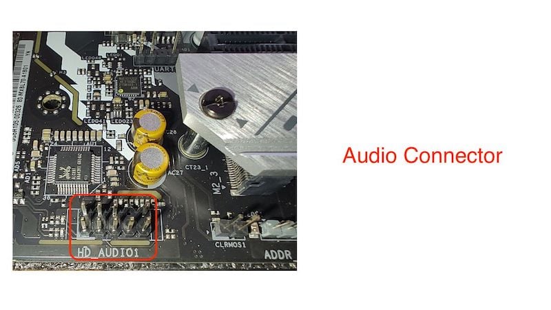
The front panel sound cable is probably the longest cable on the front panel as it extends from the top of the PC case to the bottom of the motherboard and can only be connected to the motherboard in one specific way.
Other Motherboard Connectors
There are other motherboard connectors, such as the CMOS battery connector, the Molex connector, the Com-Serial header, the USB 3.1 header, and the TPM header, but in many cases these headers are not present on every single motherboard.
- Molex Connector: The Molex connector used to be included in motherboards because it was needed to power CD drives and floppy disks, but nowadays, no one uses CD drives and floppy disks anymore, so motherboard manufacturers no longer use this motherboard connector in their motherboards.
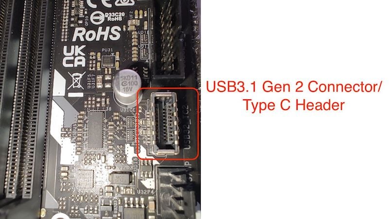
- USB3.1 Gen 2 Connector: USB3.1 has started recently coming in midrange and flagship motherboards and sometimes it is also present in budget boards. USB 3.1 is a connector that powers the USB-C port on the Front Pane. While it is popular nowadays as many cass start shipping with USB-C, it was simply not present on the motherboard from a couple of years back. It is faster than the USB 3.0 ports on the Front Panel, and it is located right below the USB 3.0 connector on the motherboard.
- TPM Connector: TPM is also known as Trusted Platform Module, and when Microsoft released Windows 11, it became mandatory that every PC/laptop must have a TPM module. Only then can Windows 11 run, but most motherboards do not have their own TPM connector and use a small chip that serves as a TPM for encryption and other things that TPM is needed for.

If you want to learn more about TPM and why Windows 11 only needs this connector, here is the link to Microsoft support to understand what TPM is.
These are all the important connectors you need to understand to build a PC. There are many more connectors on the motherboard, but these are the most important ones you should know.
FAQs about Motherboard Connectors
1. What is the function of Motherboard Connectors?
Motherboard connectors are used as a building block for your computer. They connect everything from the PC to the power supply and other connectors on your case. Motherboard connectors are used to supply power to your CPU and GPU while also supplying power to the motherboard. They also serve as a physical interface between your input and output devices and the motherboard.
2. Why do we use an ATX 24-pin power connector?
The 24-pin ATX power connector is used to supply power to all devices connected to your motherboard. It connects the motherboard directly to the power supply and distributes power to all components on the motherboard. In the past, the CPU was also supplied with power via the 24-pin ATX connector, but now the CPU receives power via the 8-pin EPS connector.
3. Why does every motherboard not ship with a USB Type C header?
While the new generation of motherboards is equipped with a USB-C header, most old-generation and budget motherboards do not have a Type-C header on board. There is a simple reason for this: in the past, case manufacturers did not make cases with USB ports on the front, as USB-C was a premium feature as it is faster than the USB 3.0 connector. The USB-C port on the motherboard has recently caught on and can now be found in most cases and also in inexpensive motherboards.
4. Why every motherboard connector does not connect to the PSU?
All motherboard connectors are not connected to the power supply as they are not used to power the motherboard, CPU, or GPU. There are special connectors that supply power to the CPU and motherboard, while other connectors are used for other purposes, such as connecting audio and USB peripherals, RGB devices, etc.
5. Do I need to connect both the 8-pin connectors to the motherboard?
The answer depends on the CPU. The 8-pin EPS connectors are used to power the CPU, with each 8-pin connector capable of delivering up to 235 watts of power, which is sufficient for most CPUs. However, if you are using an unlocked CPU or a Core i7, Ryzen 7, Core i9, or Ryzen 9, it is better to use both connectors. Otherwise, you can also use a single 8-pin connector.
6. What do EPS, SMPS, ATX, and SFX stand for?
EPS: Entry-Level Power Supply. This is a power connector that supplies the CPU with power.
SMPS: Switched Mode Power Supply is another name for PSU (Power Supply Unit).
ATX: Advanced Technology Extended is a power supply motherboard configuration for motherboards.
SFX: Small Form Factor, it is the standard that is used in power supply, these power supplies are popularly used in cases that are based on Micro ATX standard and Mini ITX standard.
